
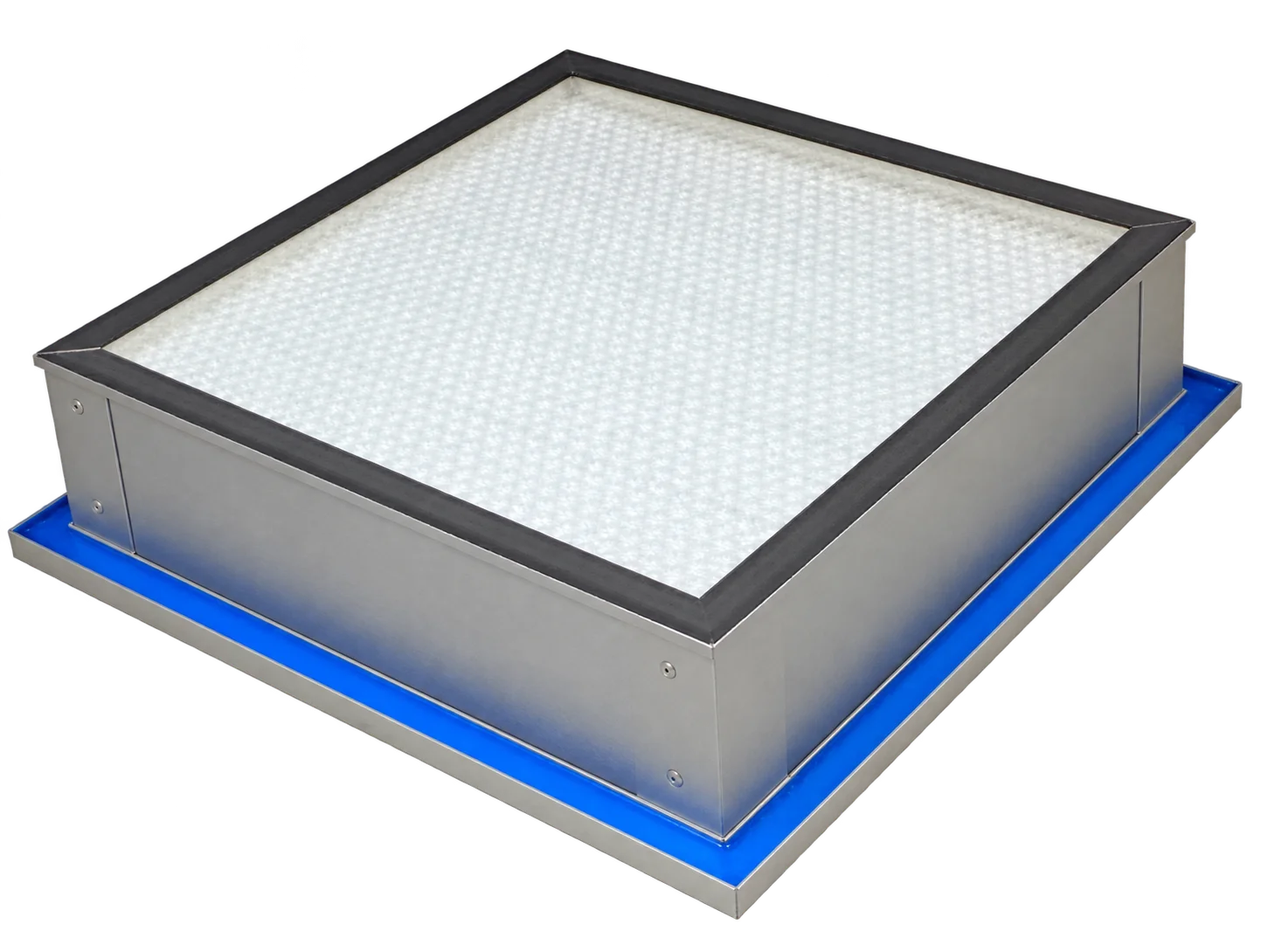
Gel Seal
HEPA / ULPA Filters
Liquid-seal filtration for matching knife-edge housings.
Aluminium-frame filters with mini-pleat glass fibre media and a gel-seal interface. Select the depth range, then match the dimensions and airflow to your equipment.
- Selected depth
- 78 mm
- Frame
- Aluminium
- Seal
- Gel seal / knife-edge interface
- Initial pressure drop
- 110 / 120 / 140 Pa
A gel-seal interface.
A configuration for your equipment.
Perimeter gel seal
The housing knife edge enters the filter’s gel channel to form the perimeter seal. Match the channel and knife-edge dimensions before ordering.
Aluminium frame & glass fibre media
Mini-pleat glass fibre paper is housed in an aluminium frame with epoxy-painted aluminium protective grids on both sides.
Depth and mounting choices
Choose 78 mm, 90 / 93 mm or 104 mm specifications. The 90 / 93 mm range offers top-gel and side-gel configurations.
Construction & technical parameters
78 mm configuration
- Depth range
- 78 mm
- Available grades
- H13 / H14 / U15
- Frame
- Aluminium
- Medium
- Mini-pleat glass fibre paper
- Protective grids
- Double-sided epoxy-painted aluminium grids
- Seal
- Gel seal
- Recommended final pressure drop
- 600 Pa
- Maximum final pressure drop
- 1000 Pa
- Initial pressure drop
- H13: 110 Pa / H14: 120 Pa / U15: 140 Pa
90 / 93 mm configuration
- Depth range
- 90 / 93 mm
- Frame
- Aluminium
- Medium
- Mini-pleat glass fibre paper
- Protective grids
- Double-sided epoxy-painted aluminium grids
- Seal
- Polyurethane gel
- Recommended final pressure drop
- 600 Pa
- Maximum final pressure drop
- 1000 Pa
- Initial pressure drop
- ≤220 Pa
- Seal position options
- Top gel / side gel
104 mm configuration
- Depth range
- 104 mm
- Available grades
- H13 / H14 / U15
- Frame
- Aluminium
- Medium
- Mini-pleat glass fibre paper
- Protective grids
- Double-sided epoxy-painted aluminium grids
- Seal
- Gel seal
- Recommended final pressure drop
- 600 Pa
- Maximum final pressure drop
- 1000 Pa
- Initial pressure drop
- H13: 110 Pa / H14: 120 Pa / U15: 140 Pa
Find the fit for
your installation.
Select a depth range and a specification row to prepare your enquiry.
78 mm · H13
| Grade | W × H × D (mm) | Airflow (m³/h) | Initial pressure drop (Pa) | Filter area (m²) | Enquire |
|---|---|---|---|---|---|
| H13 | 305×305×78 | 150 | 110 | 2.7 | |
| H13 | 457×457×78 | 340 | 110 | 6.2 | |
| H13 | 305×610×78 | 300 | 110 | 5.5 | |
| H13 | 610×610×78 | 600 | 110 | 11 | |
| H13 | 610×762×78 | 750 | 110 | 13.7 | |
| H13 | 610×914×78 | 900 | 110 | 16.5 | |
| H13 | 610×1220×78 | 1200 | 110 | 22 |
78 mm · H14
| Grade | W × H × D (mm) | Airflow (m³/h) | Initial pressure drop (Pa) | Filter area (m²) | Enquire |
|---|---|---|---|---|---|
| H14 | 305×305×78 | 150 | 120 | 2.7 | |
| H14 | 457×457×78 | 340 | 120 | 6.2 | |
| H14 | 305×610×78 | 300 | 120 | 5.5 | |
| H14 | 610×610×78 | 600 | 120 | 11 | |
| H14 | 610×762×78 | 750 | 120 | 13.7 | |
| H14 | 610×914×78 | 900 | 120 | 16.5 | |
| H14 | 610×1220×78 | 1200 | 120 | 22 |
78 mm · U15
| Grade | W × H × D (mm) | Airflow (m³/h) | Initial pressure drop (Pa) | Filter area (m²) | Enquire |
|---|---|---|---|---|---|
| U15 | 305×305×78 | 150 | 140 | 2.6 | |
| U15 | 457×457×78 | 335 | 140 | 5.8 | |
| U15 | 305×610×78 | 300 | 140 | 5.2 | |
| U15 | 610×610×78 | 600 | 140 | 10.4 | |
| U15 | 610×762×78 | 750 | 140 | 13 | |
| U15 | 610×914×78 | 900 | 140 | 15.6 |
90 / 93 mm
| W × H × D (mm) | Flange back dimensions (mm) | Airflow (m³/h) | Initial pressure drop (Pa) | Enquire |
|---|---|---|---|---|
| 320×320×93 | — | 400 | ≤220 | |
| 484×484×93 | — | 800 | ≤220 | |
| 630×630×93 | — | 1200 | ≤220 | |
| 610×610×90 | 570×570 | 1100 | ≤220 | |
| 1210×610×90 | 1170×570 | 2200 | ≤220 | |
| 660×345×90 | 610×305 | 500 | ≤220 | |
| 650×660×90 | 610×610 | 1100 | ≤220 | |
| 802×650×90 | 762×610 | 1600 | ≤220 | |
| 955×650×90 | 915×610 | 2000 | ≤220 |
Dimensions show the actual depth of each model. A dash indicates that flange back dimensions are not listed.
104 mm · H13
| Grade | W × H × D (mm) | Airflow (m³/h) | Initial pressure drop (Pa) | Filter area (m²) | Enquire |
|---|---|---|---|---|---|
| H13 | 305×305×104 | 150 | 110 | 2.7 | |
| H13 | 457×457×104 | 340 | 110 | 6.2 | |
| H13 | 305×610×104 | 300 | 110 | 5.5 | |
| H13 | 610×610×104 | 600 | 110 | 11 | |
| H13 | 610×762×104 | 750 | 110 | 13.7 | |
| H13 | 610×914×104 | 900 | 110 | 16.5 | |
| H13 | 610×1220×104 | 1200 | 110 | 22 |
104 mm · H14
| Grade | W × H × D (mm) | Airflow (m³/h) | Initial pressure drop (Pa) | Filter area (m²) | Enquire |
|---|---|---|---|---|---|
| H14 | 305×305×104 | 150 | 120 | 2.7 | |
| H14 | 457×457×104 | 340 | 120 | 6.2 | |
| H14 | 305×610×104 | 300 | 120 | 5.5 | |
| H14 | 610×610×104 | 600 | 120 | 11 | |
| H14 | 610×762×104 | 750 | 120 | 13.7 | |
| H14 | 610×914×104 | 900 | 120 | 16.5 | |
| H14 | 610×1220×104 | 1200 | 120 | 22 |
104 mm · U15
| Grade | W × H × D (mm) | Airflow (m³/h) | Initial pressure drop (Pa) | Filter area (m²) | Enquire |
|---|---|---|---|---|---|
| U15 | 305×305×104 | 150 | 140 | 2.6 | |
| U15 | 457×457×104 | 335 | 140 | 5.8 | |
| U15 | 305×610×104 | 300 | 140 | 5.2 | |
| U15 | 610×610×104 | 600 | 140 | 10.4 | |
| U15 | 610×762×104 | 750 | 140 | 13 | |
| U15 | 610×914×104 | 900 | 140 | 15.6 | |
| U15 | 610×1220×104 | 1200 | 140 | 22 |
Choose a specification row.
Match the filter
and housing interface.
Full external dimensions
Measure width, height and depth. The 90 / 93 mm group contains two actual depths; use the full dimensions in the specification table.
Knife-edge and gel channel
Provide a drawing of the housing interface, knife-edge position and insertion depth. Select top gel or side gel for the 90 / 93 mm range.
Access and operating conditions
Check the removal path and handling clearance. Send the required airflow, quantity and operating conditions with your enquiry.
For compatible clean-air equipment.
Fan filter units
Match the gel interface, frame dimensions, airflow and pressure allowance to the FFU design.
Terminal supply housings
Use with a matching knife-edge housing and upstream filtration selected for the air-handling system.
Clean-air equipment replacements
Provide the existing filter dimensions and interface drawing so the replacement configuration can be reviewed.
Protect the media.
Keep the gel channel clean.
Handle by the frame
Inspect the frame, protective grids and gel channel before fitting. Support the frame and avoid pressure on the filter medium.
Align the sealing interface
Keep the filter parallel to the mounting surface as the knife edge enters the gel channel. Use the insertion depth specified for the housing and keep debris out of the gel.
Monitor in service
Record initial pressure drop at operating airflow. Recommended final pressure drop is 600 Pa; maximum final pressure drop is 1000 Pa. Replace earlier when required by the system or filter condition.
Product questions, answered.
Which depth ranges are available?
The range includes 78 mm, 90 / 93 mm and 104 mm models. The 90 / 93 mm group has three 93 mm models and six 90 mm models.
Which grades are listed for 78 and 104 mm?
Both offer H13, H14 and U15. The 78 mm U15 selection lists six face sizes; 104 mm U15 lists seven. Use the grade-specific table for the available dimensions.
Are top-gel and side-gel options available?
Yes. The 90 / 93 mm range offers both. Select the required position in the enquiry and include the housing interface drawing.
Can these replace a gasket-sealed filter directly?
The filter must match the housing’s knife-edge and gel-channel interface. Check the complete mounting arrangement as well as the external dimensions.
What should I send for a quotation?
Select a specification row, enter the quantity and add the operating requirements. Include the housing drawing or existing filter label in your email.
Send your size.
Let’s confirm the fit.
Tell us the dimensions, quantity and operating requirements. Include photos or drawings in your email so we can review the configuration.
Prefer email? Fill in the short brief to prepare a message in your email app. Add any files before sending.